|
|
version 1.0.0
Parametric Hurricane Modeling System
|

|
|
|
version 1.0.0
Parametric Hurricane Modeling System
|
|
In this section of the documentation are introduced the features of PaHM currently implemented in the system while, in section [Conclusions and Future Considerations] are discussed future features and capabilities of PaHM.
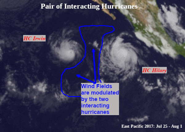
The presence of multiple TC storms in an oceanic basin is not a rare phenomenon as one could expect but it happens frequently. Some of the most recent examples of such storms are: (a) Hurricane Laura and Tropical Storm Marco (Gulf of Mexico, 2020), (b) Hurricane Irwin and Hurricane Hilary (East Pacific basin, 2017), shown in Figure [11], (c) Hurricane Madeline and Hurricane Lester (Central Pacific basin, 2016), (d) Hurricane Iselle and Hurricane Julio (Eastern Pacific basin, 2014) and (e) Tropical Storm Bonnie and Hurricane Charley (Gulf of Mexico, 2004). During the active TC periods, \(\sim 10\% - 57\%\) of TCs form in the presence of at least one other pre-existing TC in the same basin (Schenkel 2017). It is therefore important to account for the effects of multiple storms in the same basin and their interaction.
As shown in Figure [11], both the two storms modulate the wind field therefore, this effect needs to be taken into consideration when generating the wind fields. PaHM uses a simple inverse distance weighted interpolation (IDW) to determine the final wind field in the area affected by both storms. The weights in the IDW interpolation are calculated in respect of the location of the "eye" of the storms.
When the cyclones are close to each other, there is the possibility that their centers will circle each other cyclonically about a point between the two systems due to their cyclonic wind circulations. The two vortices will be attracted to each other, and eventually spiral into the center point and merge. When the two vortices are of unequal size, the larger vortex will tend to dominate the interaction, and the smaller vortex will circle around it. This effect is known as the Fujiwhara effect. PaHM is not designed to deal with this type of situations and assumes that the wind fields are just modulated without considering the detailed physical interactions between the storms.
|
Figure 11: CO-OPS wind and water level observation locations.
PaHM for its coupling configuration uses the National Unified Operational Prediction Capability (NUOPC) layer framework to exchange the generated wind fields with the other models via its own NUOPC Cap. The NUOPC Cap is a Fortran module that is used to interface to a model in a NUOPC based coupled system that comprises from NUOPC subroutines that are called during the three model phases: Init Phase (model initialization), Run Phase (model run) and Finalize Phase (model finalize part). Each model that uses the NUOPC layer should have these three subroutines available in their codebase.
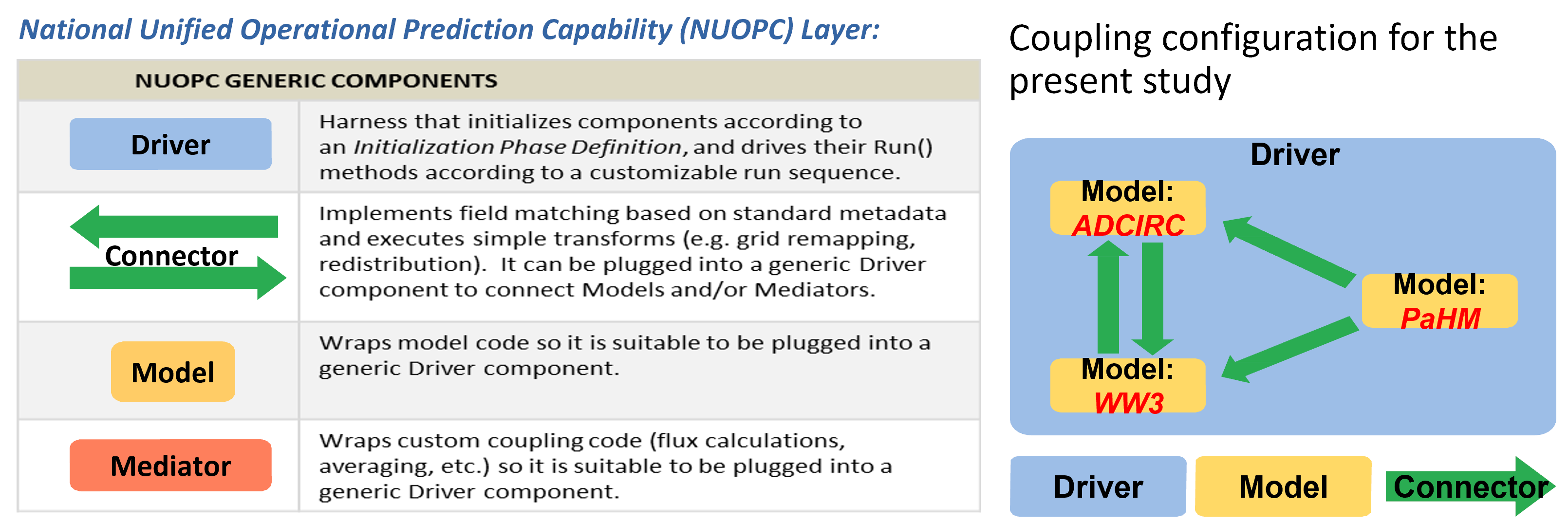
NUOPC is a software layer built on top of the Earth System Modeling Framework (ESMF). ESMF is a modeling framework that provides data structures, interfaces, and operations for building coupled models from a set of components. NUOPC refines the capabilities of ESMF by providing a more precise definition of what is a model component and how components should interact and share data in a coupled system. Furthermore, the NUOPC software layer is designed to work with High Performance Computing (HPC) models written in Fortran (as is PaHM) and are based on a distributed memory model of parallelism (MPI) The NUOPC Cap light-weight software layer on top of the model code, making calls into it and exposing model data structures in a standard way. Figure [12] shows all available generic components defined in the NUOPC layer (left panel) while, on the right panel are shown the components currently available in PaHM and the coupling configuration of PaHM with ADCIRC and WaveWatch III (not used here).
|
| Figure 12: NUOPC Cap definition and coupling configuration for the Hurrcane Florence case study. |
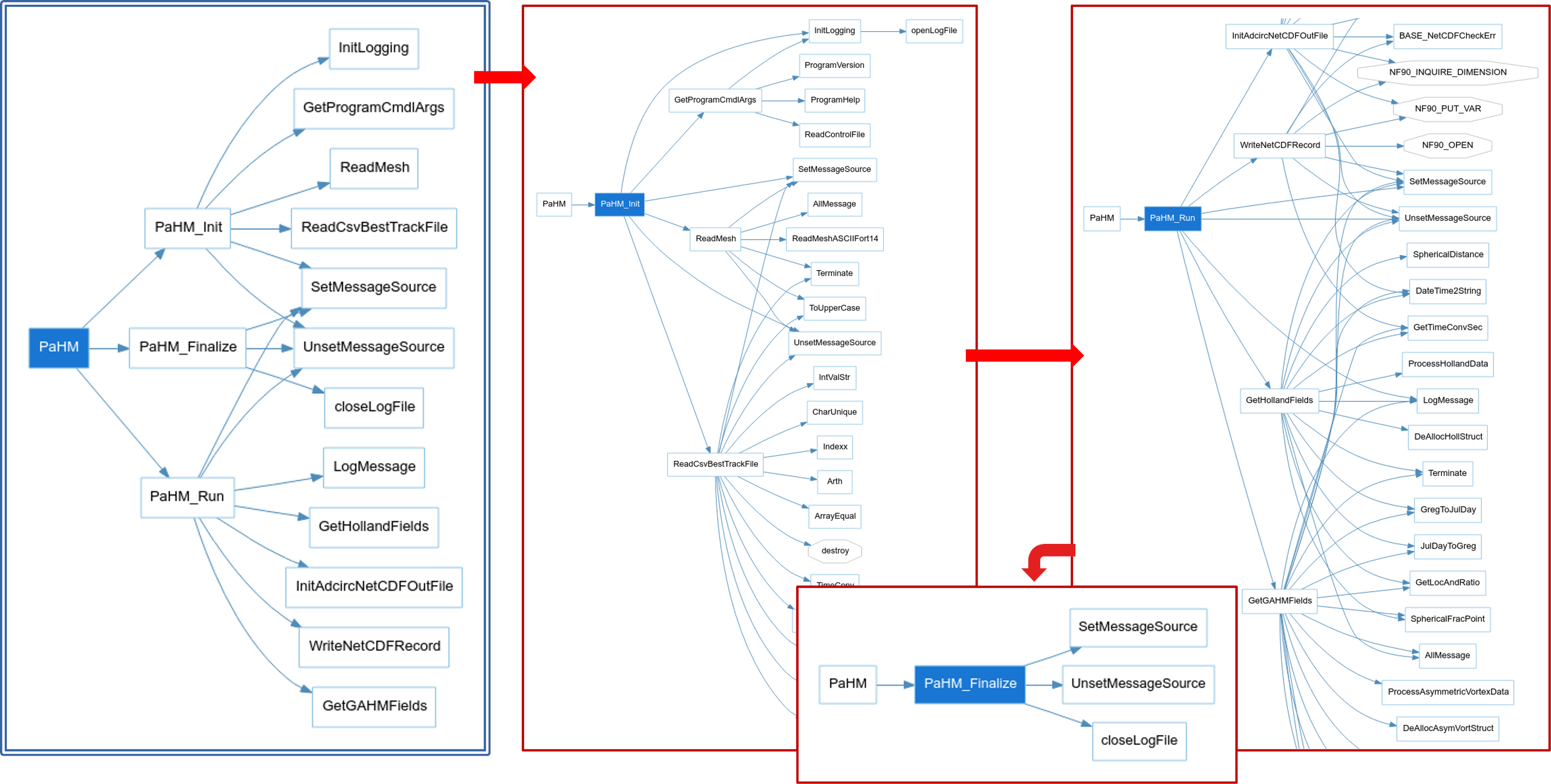
The PaHM NUOPC Cap during its "Init Phase" creates the domain for the data exchange (as an ESMF_Mesh structure), defines and advertises the fields to be exchanged and initializes PaHM by calling its "Init" subroutine (Figure [13]). During the "Run Phase", the NUOPC Cap advances PaHM's computations in time by calling its "Run" subroutine (Figure [13]). The defined fields are exported in this stage at the specified coupling intervals (defined in nems.configure file) while, the simulation period of the coupled system is pre-defined in the model_configure file (see section [[intro_conf_coupled]]). During the "Finalize Phase", the NUOPC Cap calls PaHM's "Finalize" subroutine (Figure [13]) to free still allocated memory, close any open files and the log system, and finalize the creation of the output NetCDF file that contains all the computed wind data.
|
| Figure 13: PaHM code flowchart showing the three stages of the NUOPC coupling interface. |